Do's and Dont's for Application of Supramar-Anti-cavitation-Groove
To help identifying successful applications this new chapter will be an ongoing list of illustrative examples which
work
dont work
Reminder of necessary conditions for successful implementation:
1. the groove's width must give a Reynold-number of Re > 20'000 with length = width, velocity = fluid velocity, kinematic viscosity = fluid value. Re is defined as the expression
Re = velocity * length / kinematic_viscosity
2. the groove's location on the body's surface must be entirely upstream of the cavitation inception point (without groove)
If the condition for location upstream of cavitation inception point is not reached, then the fluid will go over the groove separated by a cavitation bubble and the existence of a groove whatsoever will not have any influence
If the condition for location is met, but the condition for width is not met, then again no mixing layer will be produced, but possibly cavitation will set in at the groove.
some applications and how to change profiles for successful application of Supramar-Anti-cavitation-Groove:
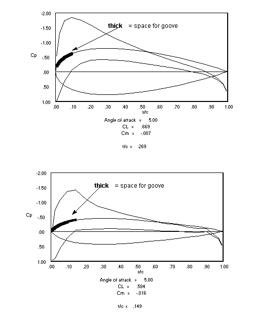
Rudder profile
On top we have the original unmodified profile for a rudder application. because cavitation inception point is very near leading edge there is not enough space upstream of this point for placing a Supramar Ant Cavitation Groove..
On the bottom we have the same rudder profile modified at the leading edge, shifting the cavitation inception point to 15% chord position and thereby allowing for placement of the Supramar groove. The price to pay is having leading edge cavitation for high angles of attack (instead of having this rigth from small angles of attack on)
waterjet impeller blade profiles
Another example is design of the profile for the blades of a waterjet impeller. The original profile with straight skelettal line and its modification at the leading edge is shown below.
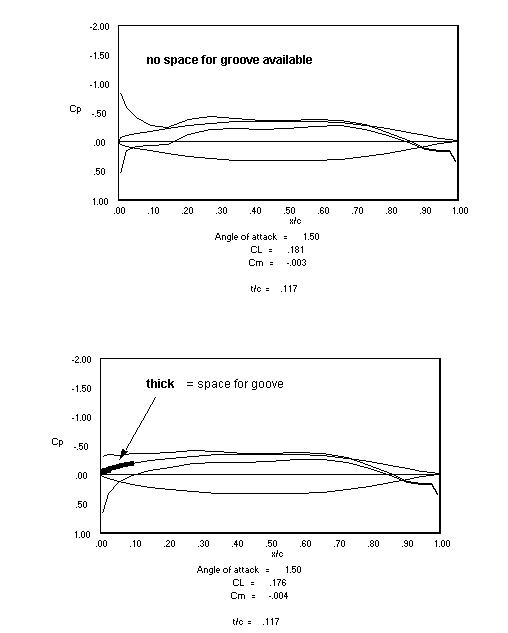
The original unmodified profile shows leading edge cavitation even for very small angles of attack. by modification of the profile near the leading edge (having a sharper profile nose) it was possible to shift cavitation inception below angles of attack < 1.5 degrees to about a chord position of 10-20%.It was at the time not considered to cover a sufficient range of angle of attack for the suction side of the profile for real high speed applications. So next alternative was introduction of a camber in order to shift the cavitation inception point on the suction side back also for higher angles of attack.
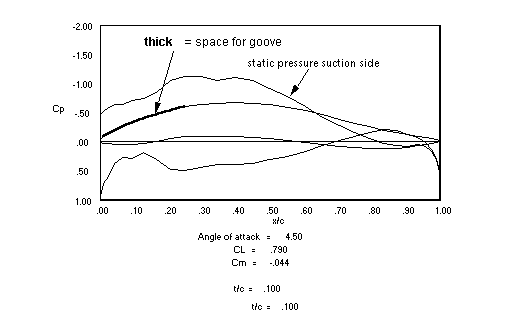
On top we have the positive result introducing camber of the skelettal line. As is demonstrated however to assure clean shift of cavitation inception over the whole range of angles of attack up to maximum, in addition to introducing camber some small but precise modification of the leading edge profile are neccessary
Summary:
For profiles with very small thickness camber and local correction of leading edge profile concentrate on modification of the sceletal line for camber and leading edge. Without such profile changes a straight and thin profile obviously is not a promising case for application of Supramar Anti Cavitation Groove.
Legend:
The pictures show the profile and the static pressure suction and pressure side of the profile (PANDA by Desktop Aeronautics, Inc)